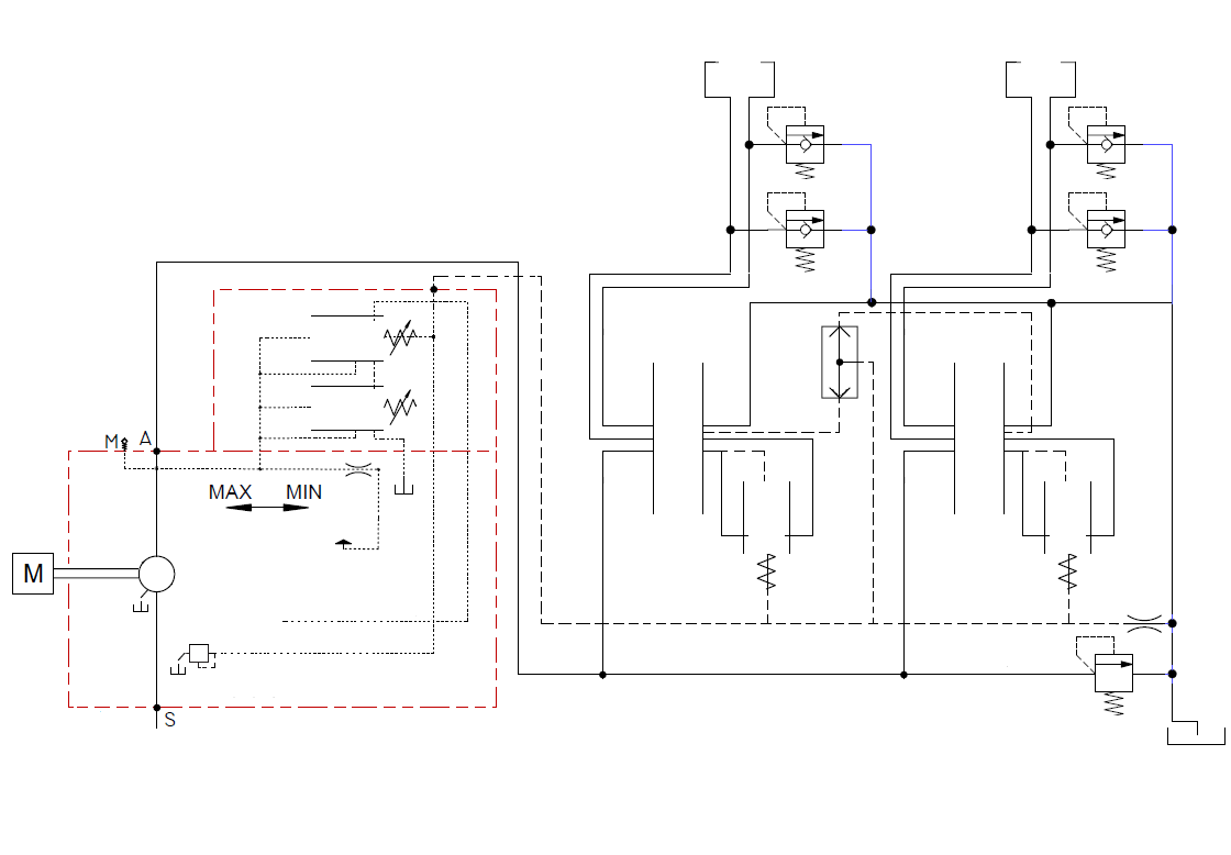
Load-sensing hydraulic system with power control and post-compensation
© LsHydraulics.ru, 2020 -
When using the site materials link to the source is required.
Load-sensing hydraulic system with power control and post-compensation

Initiate. When the directional control valves are in the neutral position there is standby pressure in the system. This pressure is mainly determined by the spring force of the flow control valve (1). The pump displacement decreases to the minimal volume from the initial maximal value. Minimal flow in the system is needed for cooling, supplying standby pressure, compensation of internal leakages and lubrication purposes. The swash plate in standby mode should not reach a neutral position. This can be realized either with a mechanical restrictor or with an orifice inside the control piston. The orifice opens a way for oil to flow out of the control piston when the swash plate moves closer to the neutral position. Opening the way for oil causes a pressure drop. The pump displacement stops decreasing. Power loss in this mode is minimal, because flow and pressure are too low.
Initiate. If the directional control valve of motor 1 (dcv1) is opened and the directional control valve of motor 2 (dcv2) is closed, then load pressure will be passed through the signal line from motor 1 to the common shuttle valve (shv) and move the valve to the upper position. Then load pressure impacts on the flow control valve (1) from the spring side and reinforces the spring action to shift this valve to the left side position. Now the channel towards the control piston is closed. The pump output pressure increases according to the load and impacts on the bias piston. The pump output flow increases until the value of differential pressure Δp does not overcome the spring force action of the flow control valve (1). When the spring force is exceeded, the flow control valve (1) is shifted to the right side position against the spring action and opens the channel towards the control piston. Now pressure impacts on this piston. The output flow decreases, the flow control valve (1) is shifted to the left side position and closes the channel towards the control piston. Thus, the pump provides pressure according to the request (load) of motor 1 plus the spring force of the flow control valve. The pump output flow depends on the load, the spring force setting and the orifice size of the directional control valve. Internal leakages can cause insignificant fluctuation of the pump swash plate for their compensation. Power loss is determined by the value of differential pressure - Δp.
Initiate. If motor 2 is activated - the directional control valve is opened - and the load of this motor is more than motor 1's load then the shuttle valve will be moved to the lower position and open the signal line to provide the load signal from motor 2 to the flow control valve (1). The pump also increases the output flow according to this request. The pressure compensator (pc1) installed on the outlet of the directional control valve (1) automatically restricts the delivery orifice to prevent an increase of flow through motor 1 since all compensators get the signal pressure from the highest load actuator. Power losses arise from the differential pressure value - Δp plus the difference between the load pressure of motor 2 and the load pressure of motor 1.
Initiate. Since a hydraulic system most often requires either high pressure and low flow or low pressure and high flow, the system can be equipped with an engine that does not provide power to obtain maximum flow and maximum pressure at the same time. In this case, torque limiting control or horsepower control is applied to prevent the engine from lugging. Torque limiting control can be realized in different ways. Here is considered the situation when the pressure relief valve (torque limiting valve - tlv) is installed in the signal line. The cutoff setting of this valve depends on the swashplate position due to their mechanical linkage. Increasing the load on motor 1 increases the swash plate angle (output flow) due to automatic load-sensing control. At a critical point (depending on the spring setting and the swash plate angle), the torque limiting valve reduces the pressure in the signal line. It causes a shift of the flow control valve (1) to decrease the pump displacement. The angle of the swash plate decreases to reduce the output flow. At the same time the mechanical action on the spring of the torque limiting valve changes - the spring is compressed with more force. The pressure in the signal line becomes higher and shifts the flow control valve (1) to the left side position. The channel towards the control piston is closed. The pump output pressure impacts on the bias piston and increases the swash plate angle (output flow). The process starts again. Pump operation in this mode is called saturation. When the pump is in saturation mode and post-compensation logic is used (pressure compensators are located downstream of the directional control valves) then the flow is always devided in proportion to the orifice sizes of the directional control valves. All functions lose speed proportionally. It happens due to a pressure drop across the directional control valves depends on the Δp pump value and remains the same for all actuators, since the spring chamber of each compensator gets the signal pressure from the function with the highest load. Pressure compensator 2 (pc2) as well as pressure compensator 1 (pc1) directly sense the signal from overloaded motor 1. If both directional control valves are fully open, then each of the actuators gets half of the pump output flow independently from their load. If the orifice sizes of the directional control valves are different, then the flow to each actuator can be calculated as the real maximum pump flow multiplied by the ratio of the actuator flow demand to the maximum theoretical flow. For example if motor 1 demands 100 l/min, motor 2 demands 25 l/min then the maximum theoretical flow rate is 125 l/min. For the real maximum pump flow rate of 100 l/min, the flow rate for motor 1: 100 / 125 * 100 = 80 l/min; for motor 2: 25 / 125 * 100 = 20 l/min. Cancel animation.
